how calculate specific load sliding speed
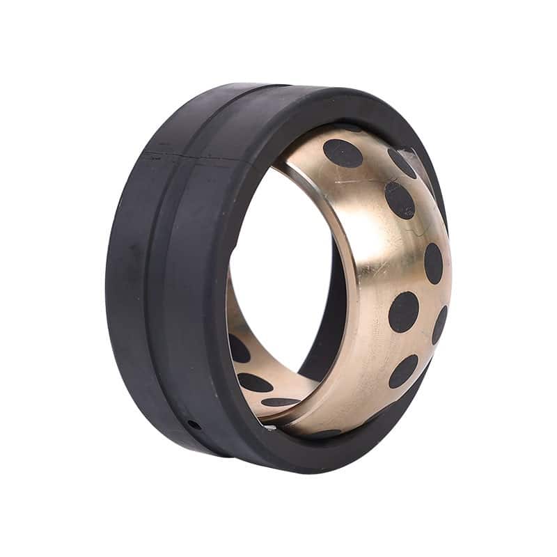
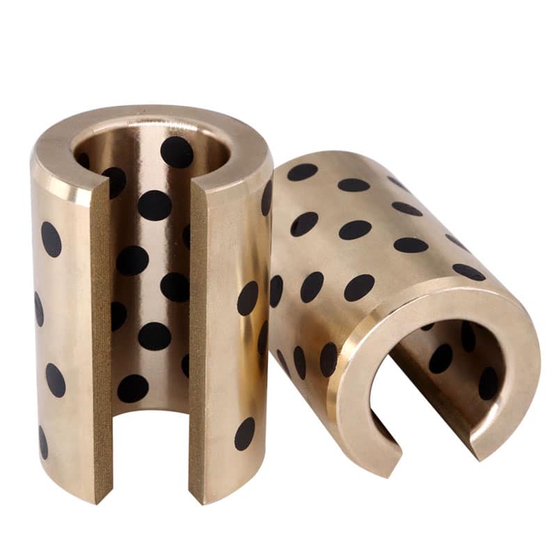
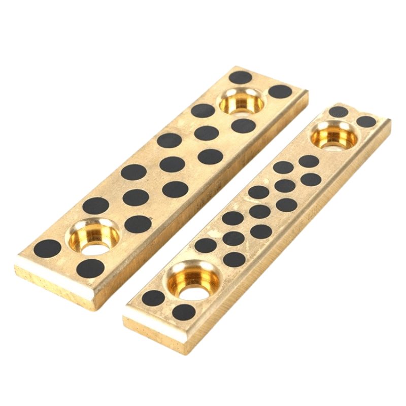
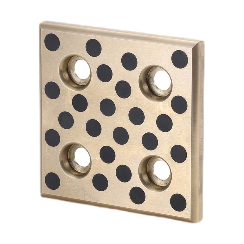
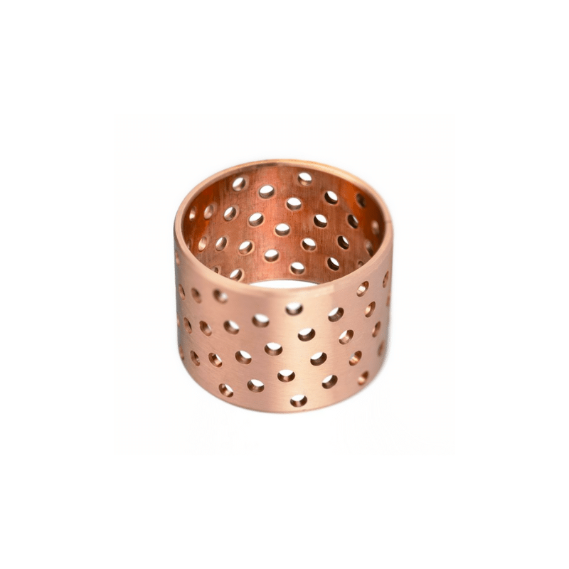
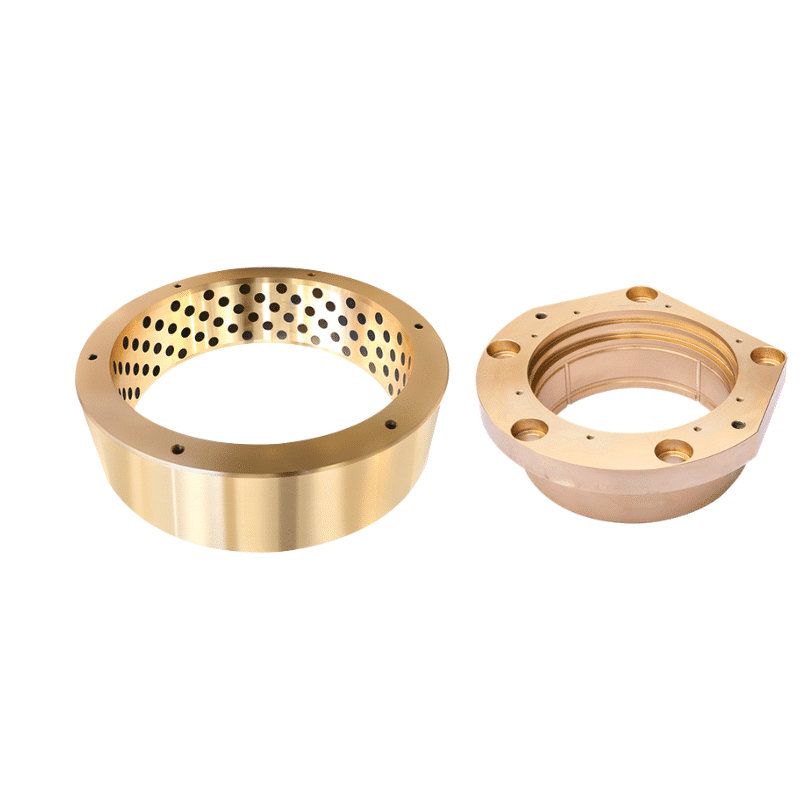
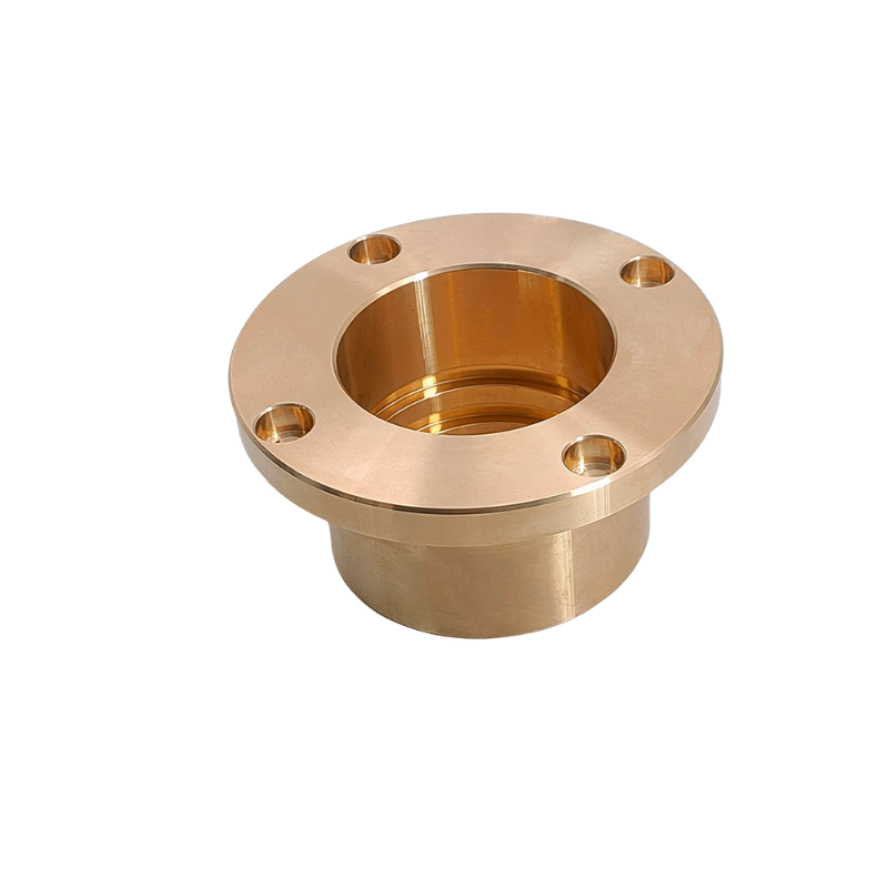
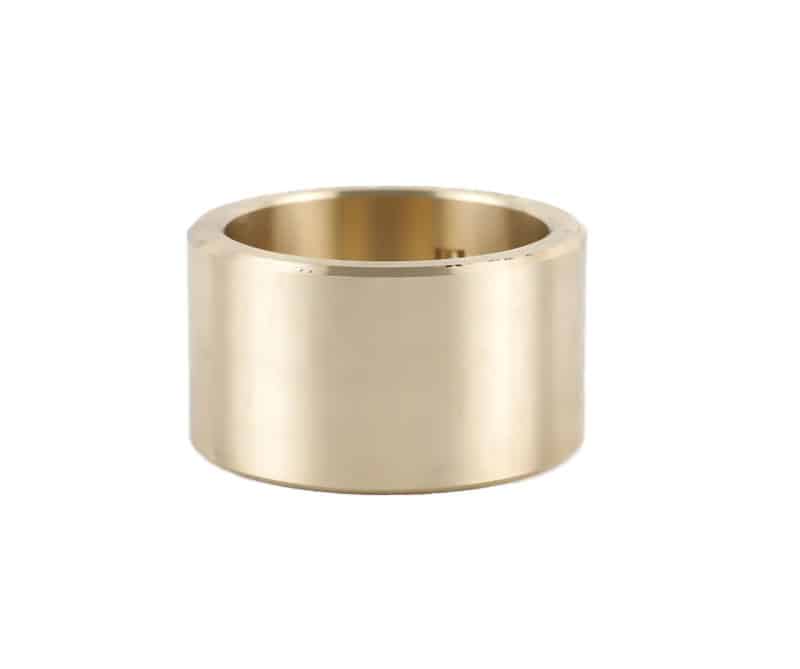
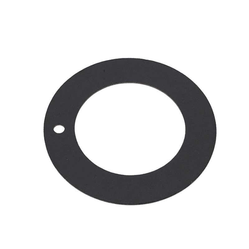
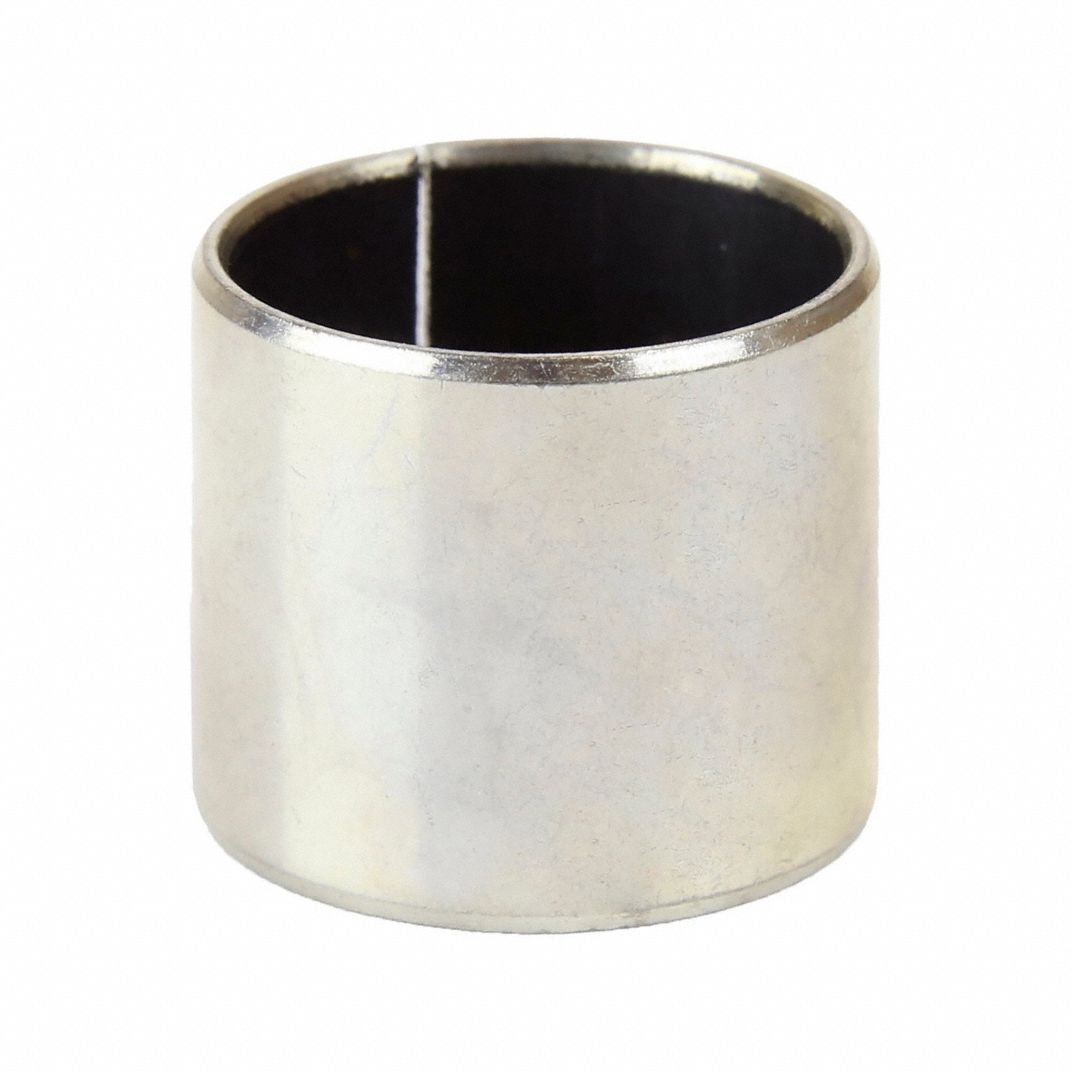
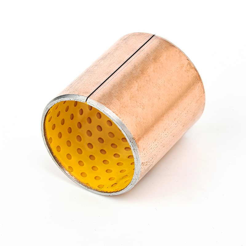
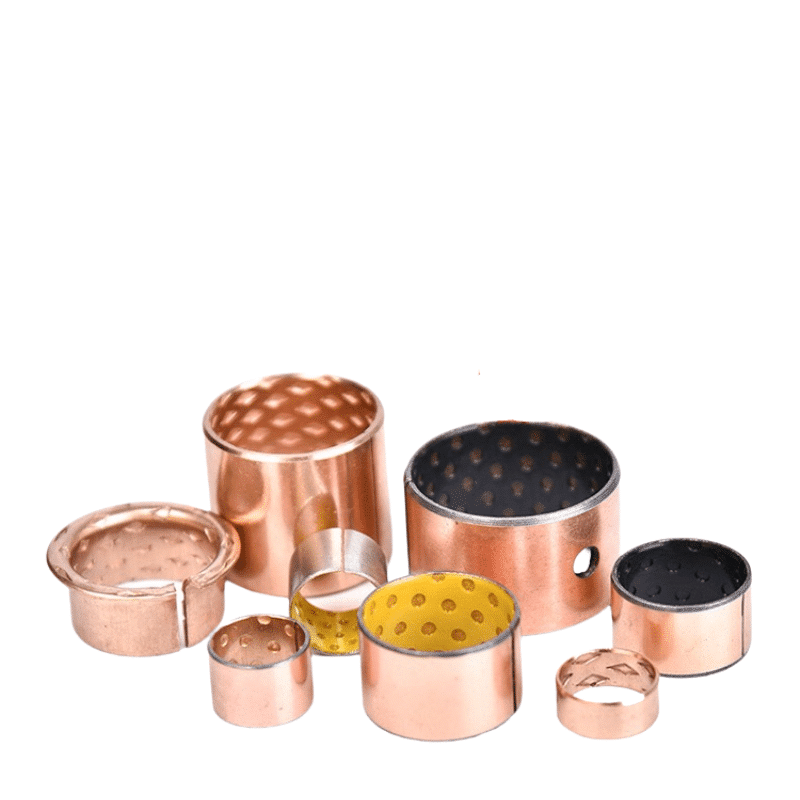
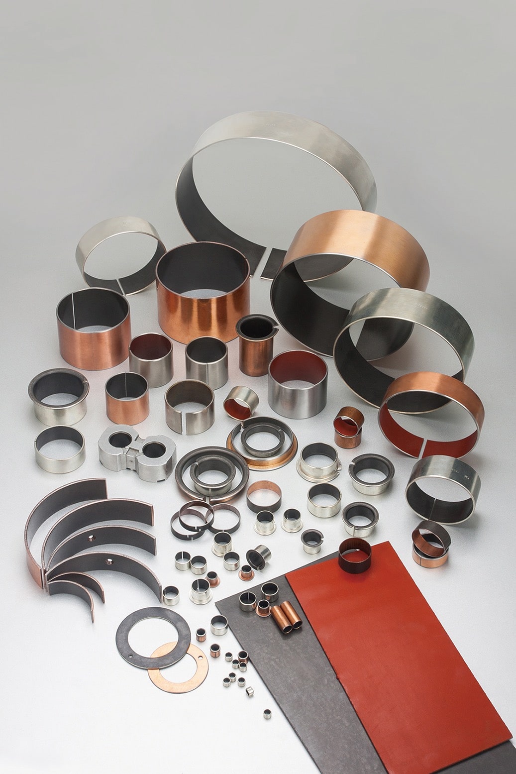
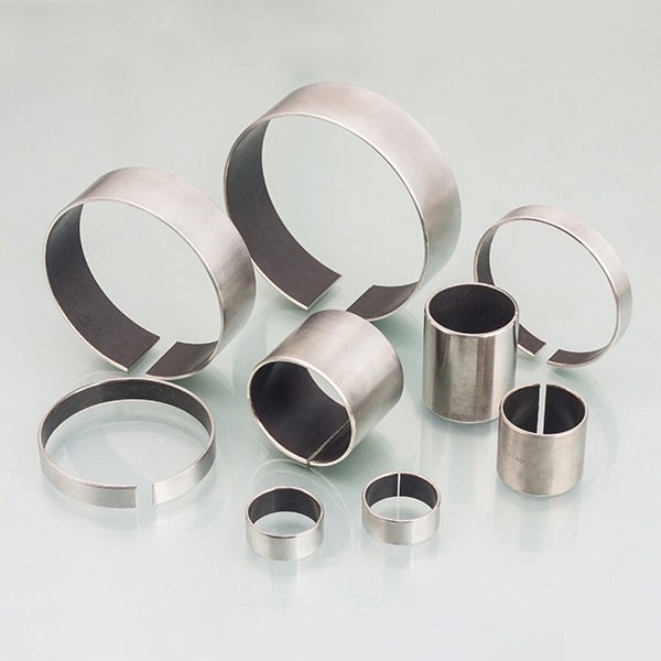
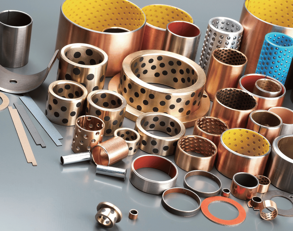
Bearings and Bushings for the Future: Precision and Customization: Our company, in bearing engineering with decades of experience, designs and develops high-precision self-lubricating bronze bearings & plain bushes. We offer a wide array of sliding bearings tailored to meet specific needs. Renowned for our expertise in custom bronze bushing and slide plate solutions, we provide an expansive selection of bushing metal alloys. Contact us today to benefit from unparalleled services at competitive prices.
how calculate specific load sliding speed

What are specific load and sliding speed?
Learn how to calculate specific loads and sliding velocities
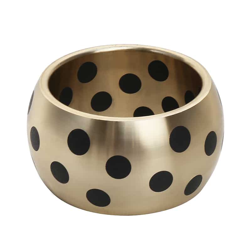
Specific load, also known as bearing pressure, is based on the force that a bearing is subjected to during its service life. It is a function of the force and contact area of the bearing material. The SI (International Standard) unit of specific load is Newton per square millimeter (N/mm2), also known as megapascal (MPa).
Sliding speed, also known as velocity (U), is the relative sliding speed between the bearing surface and the mating surface (shaft, thrust surface or liner sliding surface). The SI unit of sliding speed is meters per second (m/s).
Bearing Life Calculation – Bearing Loads & Speeds
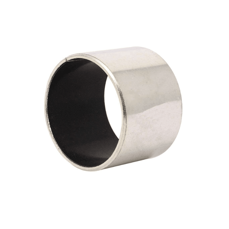
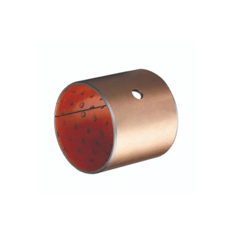
Self-lubricating Bearings, Low Friction Slide Bushing
Calculating surface speed at bearing
“The daily maintenance of bearings is mainly lubrication. With adequate assurance of lubrication, the service life of bearings can reach 5-10 years (about 20,000-30,000 revolutions) even under the most complicated working environment. However, in the case of poor lubrication, the service life of the bearing drops to about 3 months (about 9 million revolutions).” Bearing life is in you, bearing maintenance is very critical, to regularly check, oiling, and maintenance, you use the bearing environment is also very critical, his load, and so on can affect the life of the bearing

Bushing PV Calculations
PV calculation is an essential part of bushing and bearing design, particularly in self-lubricating bushings. The term “PV” stands for Pressure x Velocity, and it’s a measure of the maximum load and speed under which a self-lubricating bearing can operate. Each type of self-lubricating bearing has a maximum PV value, which should not be exceeded during operation.
Load and Life, Bushings
When selecting a bushing, it’s important to match the load and life requirements of the application with the capabilities of the bushing. If a bushing is not able to support the required load, or if its expected life is shorter than the desired lifespan, it may not be the best choice for the application. As always, consultation with a materials engineer or a reputable supplier can help guide this selection process.
How to Calculate Specific Load, Sliding Speed
Sliding speed, U, also called velocity, is usually not difficult to determine, especially in applications driven by an electric motor or engine. Velocity generates heat at the bearing/mating surface interface, which can affect the performance of the bearing over time. The greater the velocity, the greater the heat generated. Very slow or very occasional periods of relative motion may not generate enough heat to degrade the performance of the bearing material.
- Velocity, U, is measured in meters per second and is calculated based on the basic type of application.
- Continuous rotation.
- For sleeve bearings, Di = sleeve bearing bore in mm, N = shaft speed, rpm.
- For thrust washers, Do = outer diameter of the washer in mm, Di = inner diameter of the washer in mm, N = speed in rpm.
- Oscillating motion.
- For plain bearings, Di = inner diameter (mm), Nosc = shaft oscillation speed, cpm.
- For thrust washers, Do = outer diameter (mm), Di = inner diameter, Nosc (mm) = oscillation speed, cpm.
- Linear motion.
- For plain bearings and linear guides, Ls = linear travel length in mm, c = cycle speed in cpm.
Here’s how you calculate the PV value:
Pressure (P): This is the same as the specific load or bearing pressure we discussed earlier. It’s calculated by dividing the load on the bearing by the bearing’s projected area. This is usually expressed in psi (pounds per square inch) or in N/mm² (Newtons per square millimeter) in metric units.
Velocity (V): This is the surface speed of the bearing or the sliding speed, and it’s calculated by multiplying the shaft speed (in revolutions per minute or RPM) by the circumference of the bearing. This is usually measured in feet per minute (fpm) or in meters per second (m/s) in metric units.
PV Value: Multiply the specific load (P) by the sliding speed (V) to calculate the PV value. If the units of P are psi and V are fpm, the PV value is typically expressed in psi-fpm.
The PV value should be used as a guideline for the safe operating conditions of the bearing. If the actual operating conditions exceed the bearing’s maximum PV value, the bearing’s life may be shortened or it may fail prematurely. Always refer to the manufacturer’s specifications when determining the appropriate PV value for a bearing in a specific application.
Keep in mind that these calculations are simplified and do not take into account factors such as the effects of temperature, edge loading, lubrication condition, and others. Consult with an applications or materials engineer to ensure the appropriate selection and use of self-lubricating bushings.
Calculation of the surface velocity at the plain bearing
In order to design a plain bearing correctly, you need two main basic parameters: the sliding speed (v in m/s) and the load to be carried (p in N/mm²). These two parameters are added together to give the pv value, which is an important quantity in the selection of a plain bearing. Calculating the load or surface pressure is relatively simple, but calculating the surface velocity requires more formulas and parameters. This blog post will describe the most commonly encountered motion situations and the calculations they require.
Calculating surface velocities at bearing points for rotational motion
For applications where the shaft undergoes full rotation in the bearing, the peripheral velocity at the inner diameter of the bearing must be calculated. This requires the relevant bearing diameter and the number of rotations per unit time (preferably rpm). We then simply plug these values into the formula.
Formula: v(u) = π * d * n
Since the standard units used in the field of plain bearings are mm and rpm, the formula requires conversion factors.
Formula with conversion: v(u) = ( π * d * n ) / ( 1000 x 60 )
For a bearing with a diameter (d) of 20 mm and a speed (n) of 100 rpm, the surface speed is calculated as.
v(u) = π * d * n => v(u) = 3.142 * 0.002m * 1.667 1/s = 0.01m/s (numbers are rounded to two decimal places)
One source of error is unit conversion. In practice, bearing diameters are usually given in millimeters, while rotational speeds are given in rpm. The former must be converted to meters and the latter must be converted to revolutions per second. This formula returns the peripheral speed in meters per second.
Calculating the surface velocity of a bearing point with rotational or oscillating motion
Another common mode of operation for plain bearings is rotational or oscillating motion. This occurs in applications with hinges or other types of rotational motion. The shaft rotates in an alternating direction at the bearing point. The angle representing the difference in position between the two ends is the pivot angle. In these applications, the frequency of motion and the pivot angle are often the only known quantities. However, calculations for these applications also require the peripheral velocity, or the velocity of the axes relative to each other in motion. This formula takes into account the angles and is therefore a bit more complicated.
Equation: v(u) = ( n * ꞵ * d * π ) / 360
Here, ꞵ is the pivot angle. adapted to the bearing diameter (mm) and the pivot period per minute.
v(u) = (n * ꞵ * d * π) / (60 * 1000 * 360)
This equation can be used to calculate the surface velocity for pivoting applications.
Polymer plain bearings and their potential service life.
Do you need help with the design of your plain bearing? We will be happy to advise you, help you determine the various parameters, and recommend a viable bearing solution.
Self-lubricating bushing bearing life calculation
To calculate the life of a self-lubricating bushing bearing, you can use the Modified Rating Life formula, which takes into account the reliability, load, speed, and material properties of the bearing. Here’s a step-by-step guide to calculating the bearing life:
Determine the load (P) acting on the bearing.
This is the radial or axial load (in newtons) that the bearing is subjected to during operation.
Calculate the equivalent dynamic load (Peq) using the load and load direction factor (fD).
For radial bearings, Peq = P x fD
For axial bearings, Peq = P x (fD / 2)
fD is a factor that depends on the load direction and is typically provided by the bearing manufacturer. If the factor is not available, you can assume a value of 1 for purely radial loads and 1.5 for combined radial and axial loads.
Determine the basic dynamic load rating (C) of the bearing.
This value is provided by the bearing manufacturer and represents the constant load that would result in an expected bearing life of 1 million revolutions. The unit is newtons (N).
Calculate the bearing life modification factor (aISO).
This factor considers the material properties of the bearing and is usually provided by the manufacturer. If not available, a value of 1 can be used as an approximation.
Determine the desired reliability (R) of the bearing.
This is the probability that the bearing will survive without failure for the specified life. Common reliability values are 90% (L10 life), 95% (L5 life), and 99% (L1 life).
Calculate the reliability factor (a1) using the desired reliability (R).
a1 = – log(1 – R) / log(10)
For example, for L10 life (90% reliability), a1 = 1.
Determine the operating speed (n) of the bearing in revolutions per minute (RPM).
Calculate the desired bearing life (L) in hours.
This is the number of hours the bearing is expected to last without failure.
Calculate the required bearing life (Lh) in millions of revolutions.
Lh = (L x n x 60) / 1,000,000
Finally, calculate the modified rating life (Lnm) of the bearing using the following formula:
Lnm = (C / Peq)^aISO x a1 x Lh
If the calculated modified rating life (Lnm) is greater than or equal to the desired bearing life (Lh), the bearing is suitable for the given application. If not, you may need to choose a bearing with a higher load rating, adjust the operating conditions, or consider using multiple bearings to distribute the load.
Why are specific load () and sliding speed (U) important?
The two factors, MPa and U, are used to determine whether a given bearing design and bearing material selection is suitable for various application requirements. For example, by first selecting a bearing material, the designer can specify the appropriate bearing size to meet the application requirements. Alternatively, by first determining the bearing size, the designer can select a bearing material that meets the requirements of various applications.
An important factor in dry bearing design is the product of specific load (MPa) and sliding speed, called the U-factor. The U-factor, in combination with the coefficient of friction, determines the rate of heat generated by thermal friction for a given dry bearing design, which is related to the thermal resistance of the bearing material. The Bearing bushing brochure lists the U and U limits for various bearing materials.
In lubricated applications, the ability of a sleeve bearing to form a hydrodynamic lubricating film between the shaft and the sleeve bearing surface is determined by the relationship between the specific load () and sliding speed (U), the dynamic viscosity of the lubricant (centipoise) and the bearing length to diameter ratio (B/D). The relationship between these factors is: where the value of 7.5 is based on the scale factor of ISO units.
How to calculate a specific load?
To determine the bearing’s ability to resist permanent deformation in a worst-case scenario, we must first determine the maximum applied force, Fmax,. To determine the maximum force, which is critical to a robust bearing design, we must consider: expected design loads; load histories based on other similar designs; measured loads; power source information, such as torque versus speed; and shock loads. The maximum specific load, p max, is used to determine if the bearing material has sufficient load capacity to support the maximum load.
When determining the bearing life of a plain bearing bushing product, the average or weighted average bearing load, F, is used to determine if the bearing material will provide sufficient life when sliding speeds are considered. The average bearing load is calculated when the load data is limited to the minimum and maximum values. If the load range between the minimum/maximum loads is relatively small (less than 25%), then only the average of these two values is taken. If the load range is relatively large, then take the difference of 2/3 of it and add it to the minimum load to get a “conservative” average. If there is a load vs. time history, assuming a stable speed, then a weighted average can be used.
where tn and Fn are the time and load for each time/load increment and St, respectively.
When the speed varies, the number of revolutions n1, n2 … nn and Sn instead of time increments t1, t2 … tn and St.
Now that the maximum and average forces have been determined, the specific loads are easy to calculate.
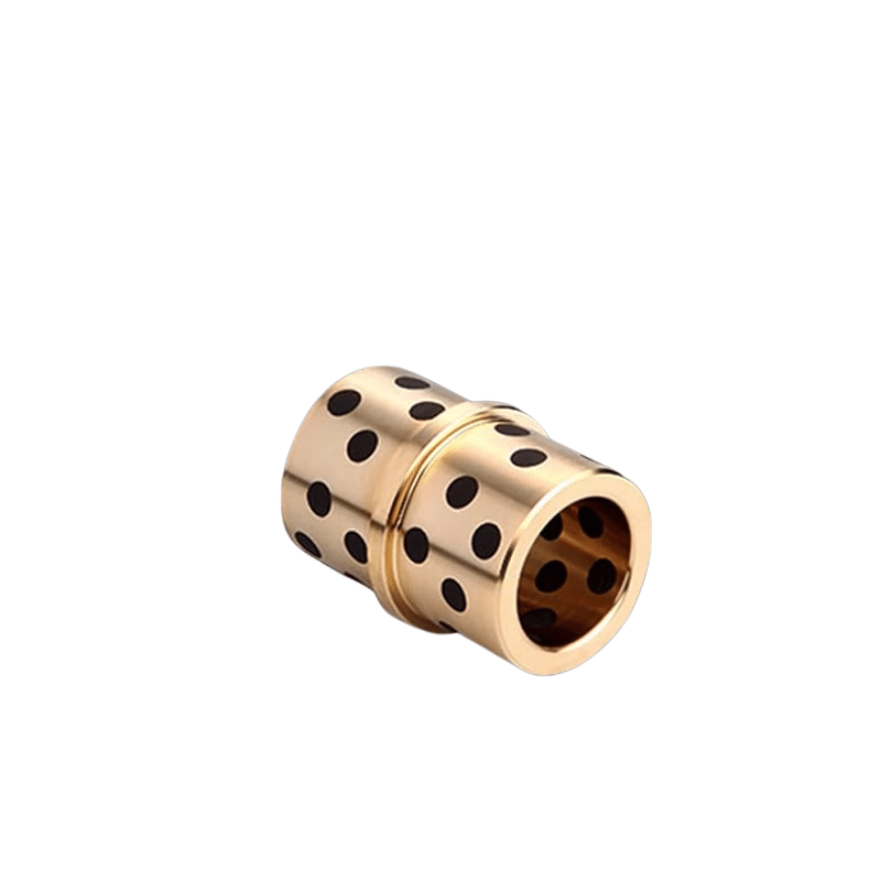
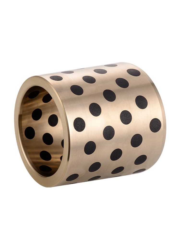
For sleeve bearings, the projected area A = Di ´ B, based on the sleeve bearing inner diameter Di, multiplied by the bearing length B.
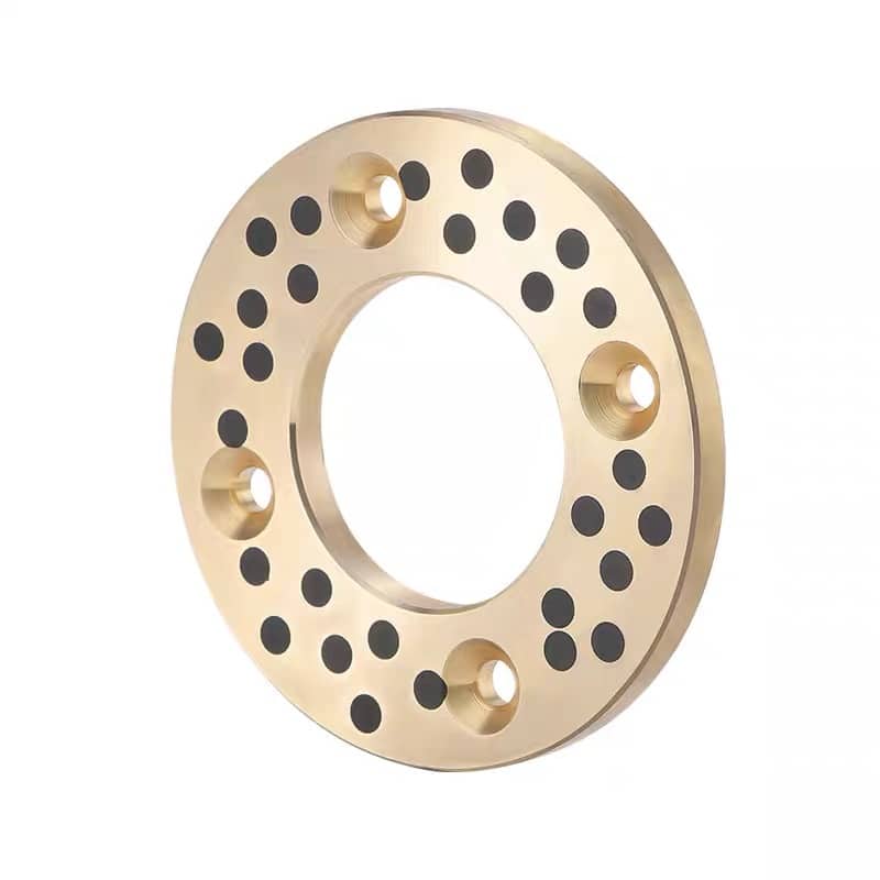
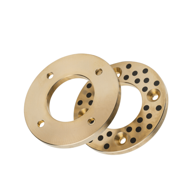
For thrust washers, A = 0.25 ´ p ´ (Do2 – Di2), where Do and Di are the outer and inner diameters of the washer, respectively.
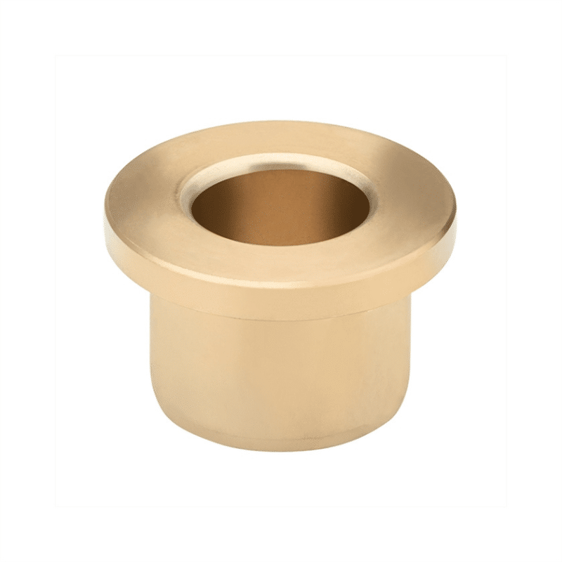
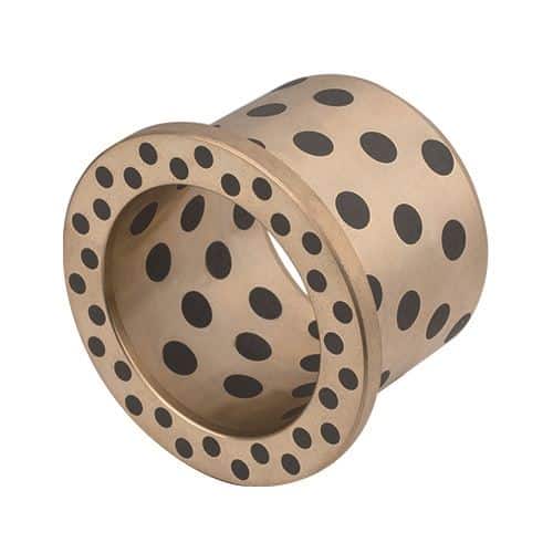
For the thrust face of the flange bearing, A = 0.04 ´ p ´ (Do2 – Di2), where Do is the outer diameter of the flange and Di is the inner diameter of the flange bearing.
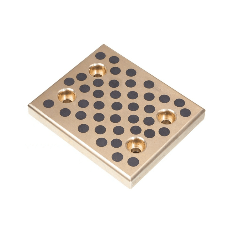
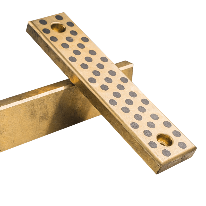
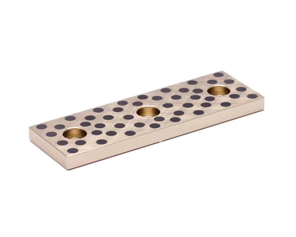
For linear slideways, A = L ´ W, where L = bearing material length; W = bearing material width.
Sliding speed, U, also called velocity, is usually not difficult to determine, especially in applications driven by an electric motor or engine. Velocity generates heat at the bearing/mating surface interface, which can affect the performance of the bearing over time. The greater the velocity, the greater the heat generated. Very slow or very occasional periods of relative motion may not generate enough heat to degrade the performance of the bearing material.
Velocity, U, is measured in meters per second and is calculated based on the basic type of application.
Continuous rotation.
For sleeve bearings, Di = sleeve bearing bore in mm, N = shaft speed, rpm.
For thrust washers, Do = outer diameter of the washer in mm, Di = inner diameter of the washer in mm, N = speed in rpm.
Oscillating motion.
For plain bearings, Di = inner diameter (mm), Nosc = shaft oscillation speed, cpm.
For thrust washers, Do = outer diameter (mm), Di = inner diameter, Nosc (mm) = oscillation speed, cpm.
Linear motion.
For plain bearings and linear guides, Ls = linear travel length in mm, c = cycle speed in cpm.
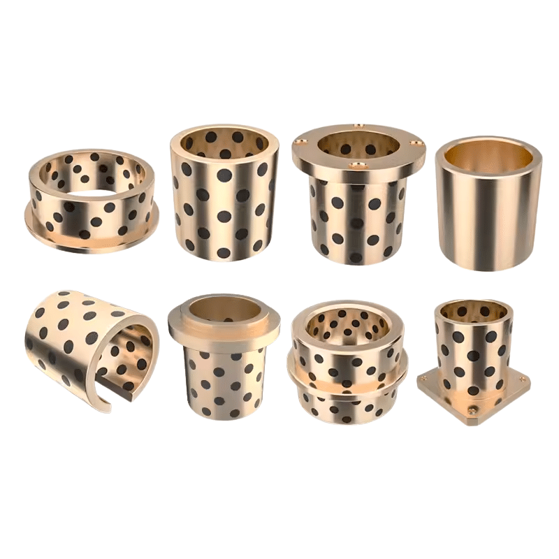
Plain Bearing Bushing Supplier
24/7 emergency callout

Solutions For Every Industry
Searching for Dependable Bushing Solutions? viiplus Has What You Need.

Design Guides, Materials
Bushing design, Comprehensive design manuals covering a range of self-lubricating materials used in all of viiplus’s manufacturing processes.

Technical Guides
Manufacturing On Demand, Technical Guides For Machining Design. Discover the latest in metal alloys, materials, and design tips for manufacturing custom machined and self-lubricating bearing parts.

Get Instant Quote
To receive your instant quote, simply upload your drawing file and choose your production process & bushing material.

Prototyping, Place Order
After you place your order, we will start the production process. You will receive updates when your order has completed production and is ready to be dispatched.

Receive Your custom Parts
We provide precision-inspected high-quality parts, packing lists and documents, and delivery tracking.